


TF100 Display Manual
TF100 Specification Document - Boyueda
Product Name: Scooter Throttle Instrument
Model: TF100

![]() This display manual is currently applicable to BOYUEDA S3-11 and Q7 PRO. For reference only.
This display manual is currently applicable to BOYUEDA S3-11 and Q7 PRO. For reference only.
1. Dimensions
- Length: 128.06 mm
- Width: 33.55 mm
- Height: 10.78 mm
- Weight: 28.00 g

2. Functions
2.1 Display Functions
- Speed display
- Battery level indicator
- Fault warning
- Headlight indicator
- Cruise control indicator
- Gear indicator
- Total mileage
- Single trip mileage
- Real-time voltage
- Operating current
- Running time
- Start mode
2.2 Communication Protocol: UART
2.3 Display Content
The display shows all the following content within 1 second of powering on, including the software version number.

3. Display Content Description
3.1 Voltage Status Level (POWER)

3.2 Multi-function Display Area

- Total mileage (ODO)
- Single trip mileage (TRIP)
- Real-time voltage (V)
- Operating current (A)
- Running time (TIME)
- Fault code (E)
3.3 Fault Status Display Area (E)
When a fault symbol
 appears, briefly press the ON/OFF button to switch to the E interface. The corresponding number on this interface represents the specific fault condition as follows:
- ERROR 1: Motor Hall sensor fault
- ERROR 2: Brake fault
- ERROR 3: No fault
- ERROR 4: No fault
- ERROR 5: No fault
- ERROR 6: Under-voltage fault
- ERROR 7: Motor phase line fault
- ERROR 8: Torque fault
- ERROR 9: Controller fault
- ERROR 10: Signal reception fault
- ERROR 11: Signal transmission fault
3.4 Speed Display Area

- Unit: mile, KM/H
- The speed signal is obtained from the Hall sensor inside the motor and sent to the instrument via the controller.
- The instrument calculates the actual speed based on the wheel diameter and signal data (the number of magnetic poles in the motor must also be set).
3.5 Gear Display Area

- Briefly press the MODE button to cycle through the gears. The higher the gear, the faster the speed.
3.6 Cruise Control Display Area

- After the motor starts, maintain the throttle for about 8 seconds to activate the cruise control symbol. The motor will maintain the current speed after releasing the throttle.
- Braking or adjusting the throttle again will deactivate the cruise control.
3.7 Start Mode Selection Display Area
- Non-zero start: NON symbol lights up
- Zero start: ZERO symbol lights up
3.8 USB Charging Icon Display Area
- When a data cable is connected to the USB port and draws more than 100 mA, the USB icon lights up.
- If the icon is flashing, it indicates intermittent charging or a load current exceeding 1000 mA, and the USB port will automatically enter protection mode.
4. Parameter Settings and Definitions
| Parameter | Description |
|---|---|
| P01 | Backlight brightness setting |
| P02 | Unit setting |
| P03 | Voltage level setting |
| P04 | Sleep time setting |
| P05 | Gear setting |
| P06 | Wheel diameter: unit in inches; precision: 0.1 |
| P07 | Speed measurement magnet count: range 1-100 |
| P08 | Speed limit setting |
| P09 | Zero start / Non-zero start setting: 0 = Zero start; 1 = Non-zero start |
| P10 | Drive mode setting |
| P11 | Pedal assist sensitivity setting |
| P12 | Start strength setting |
| P13 | Pedal assist magnet disk setting |
| P14 | Current setting |
| P15 | Under-voltage value setting |
| P16 | ODO setting |
| P17 | Cruise control setting |
| P18 | Empty |
| P19 | Empty |
| P20 | Empty |
ODO Reset: Long press the MODE button in the ODO parameter setting interface to reset ODO.
5. Button Functions
5.1 Power Off State
- Long press the power button to turn on the device.
- Briefly press the power button to switch between ODO, TRIP, VOL, fault code, current, Hall value, and running time interfaces.
5.2 Power On State
- Long press the power button to turn off the device.
- Briefly press the MODE button to switch gears.
- Long press the MODE button to control the headlight on/off.
5.3 Normal Operation State
- Simultaneously long press the power button and MODE button to enter the menu settings.
- Briefly press the power button to switch between menus.
- Briefly press the MODE button to edit the parameters in the current menu (default is incremental; long press the power button to switch between increment and decrement).
6. Parameter Values
| P01 | P02 | P03 | P04 | P05 | P06 | P07 | P08 | P09 | P10 |
|---|---|---|---|---|---|---|---|---|---|
| 3 | KM | 60V | 10 | 3 | 11 | 30 | 100 | 0 | 2 |
| P11 | P12 | P13 | P14 | P15 | P16 | P17 | P18 | P19 | P20 |
|---|---|---|---|---|---|---|---|---|---|
| 3 | 1 | 12 | 14 | 49 | ODO | 0 | 0 | 0 | 4 |
-
Original Battery For BOYUEDA E-scooters
Regular price From €349,00 EURRegular priceUnit price per€309,00 EURSale price From €349,00 EURRate payment with 0% interest


-
Original Motor(With tire) For Boyueda E-scooters
Regular price From €309,00 EURRegular priceUnit price per€449,00 EURSale price From €309,00 EURRate payment with 0% interest
Sale -
Original Front Fork Rown (Teering Shaft) For Boyueda E-scooters
Regular price €149,00 EURRegular priceUnit price per€159,00 EURSale price €149,00 EURRate payment with 0% interest
Sale -
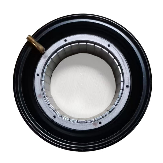
Original Rim / Hub For Boyueda E-scooters
Regular price From €149,00 EURRegular priceUnit price per -
Transparent acrylic plate for the original pedal position of Boyueda S5-11 scooter
Regular price €129,00 EURRegular priceUnit price per -
Original Steering Damper For Boyueda S5-11 / S3-11
Regular price €129,00 EURRegular priceUnit price per€105,00 EURSale price €129,00 EURRate payment with 0% interest
-
 €20OFF
Scooter Full Face Helmet
Regular price €119,00 EURRegular priceUnit price per€139,00 EURSale price €119,00 EURRate payment with 0% interest
Sale -
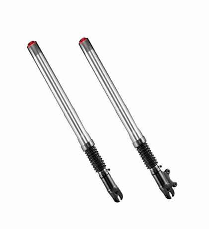
Original Front Fork For Boyueda E-scooters
Regular price From €119,00 EURRegular priceUnit price per€209,00 EURSale price From €119,00 EURRate payment with 0% interest
Sale -
Original Seat Set For Boyueda E-scooter
Regular price €109,00 EURRegular priceUnit price per€109,00 EURSale price €109,00 EURRate payment with 0% interest
-
Original Complete set of folding parts for Boyueda E-scooters
Regular price From €99,00 EURRegular priceUnit price per -
Original Motor Shaft For Boyueda E-scooters
Regular price €95,00 EURRegular priceUnit price per€115,00 EURSale price €95,00 EURRate payment with 0% interest
Sale -
Original LY 810 Display Meter with NFC Cards for Boyueda S5-11 & Q7 Pro Max E-scooters
Regular price €89,00 EURRegular priceUnit price per -
Original Seat For Boyueda E-scooter
Regular price €79,00 EURRegular priceUnit price per€109,00 EURSale price €79,00 EURRate payment with 0% interest
Sale -
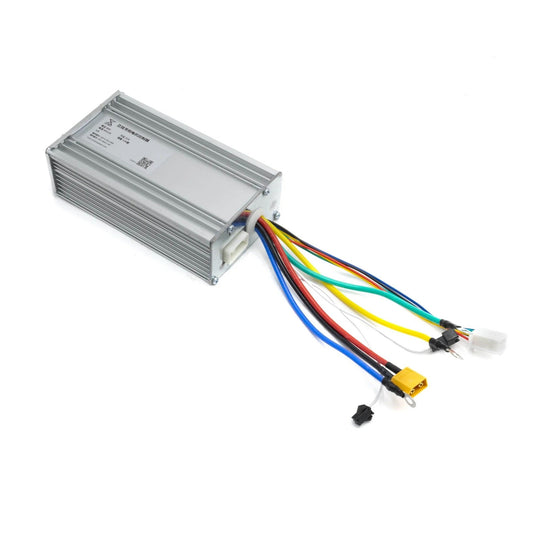
Original Controller for BOYUEDA E-scooters
Regular price From €79,00 EURRegular priceUnit price per€99,00 EURSale price From €79,00 EURRate payment with 0% interest
Sale


-
BOYUEDA S5-11 Mountain Off-Road E-Scooter Bluetooth Display with Steering Damper
 6000W Brush-Less Motor
 60V 38Ah UL certification
 120KM Max Range
 85KM/h Max SpeedRegular price €1.179,00 EURRegular priceUnit price per
€1.499,00 EURSale price €1.179,00 EURRate payment with 0% interest
Sale -
BOYUEDA S3-11 Powerful Mountain Off-Road E-Scooter
6000W Brush-Less Motor
60V 38Ah UL certification
120KM Max Range
85KM/h Max SpeedRegular price €1.079,00 EURRegular priceUnit price per€1.399,00 EURSale price €1.079,00 EURRate payment with 0% interest
Sale -
BOYUEDA Q7 Pro Max Smart Bluetooth Display City E-Scooter Foldable
3200W Brush-Less Motor
52V 28Ah UL certification
110KM Max Range
70KM/h Max SpeedRegular price €829,00 EURRegular priceUnit price per€999,00 EURSale price €829,00 EURRate payment with 0% interest
Sale -
BOYUEDA Q7 PRO Foldable City E-Scooter
3200W Brush-Less Motor
52V 19Ah UL certification
70KM Max Range
70KM/h Max SpeedRegular price €709,00 EURRegular priceUnit price per€899,00 EURSale price €709,00 EURRate payment with 0% interest
Sale


